


Controller Parameters and Features
- Features:
- – Uses analogical chip with no software inside.
- – Work only with sensored brushless motors.
- – Speed adjustable via a potentiometer
- – Adjustable acceleration deceleration
- – Loop Control
- – Fackword / Forward
- – Dynamic breaking
- – Over-current sense from external shunt resistor 100mV threshold level.
- – Overheat protection.
- – Undervoltage protection.
- – Fully Accessible Error Amplifier for Closed Loop Servo Applications
- – Adjustable PWM frequency
- – 6.25 V Reference Capable of Supplying Hall Sensor Power
I used Eagle Cad to make the schematic and the board.

New version of the schematic and it is easy to understand :

Very important !!! without the DC-DC converter(above to IR2103) the controller can not work.
This is another version with more mosfets in parallel and different drivers.
I used only N-channel mosfets in junction with IR2110 half bridge mosfet driver.
You also need a inversor gate for the Top Drives (4049)
This is the newest version with 4 mosfet in parallel per switch IR4110 but doesn`t matter what mosfet you use as the volgate and current is good for you.
The pin 3 JP8 goes to the Board 2 (Comand module) at JP20 pin 1
The pin 1 JP8 goes to Board 2 JP20 pin 2
The Pin 3 JP9 goes to the Board 2 at JP20 pin 3
The pin1 JP9 goes to the Board 2 JP20 at pin 4
The pin 3 JP10 goes to the Board 2 JP20 pin 5
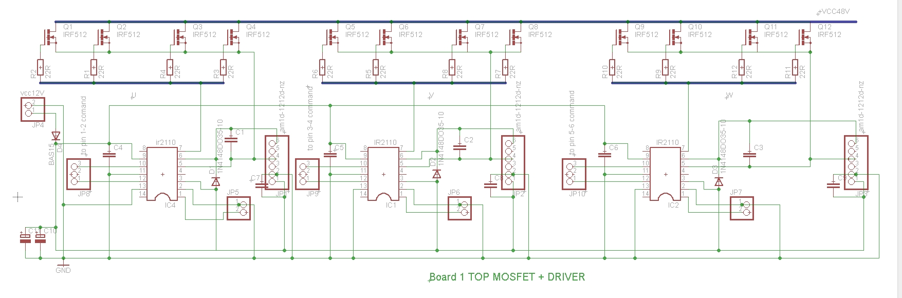
The pin 1 JP10 goes to the Board 2 jp20 pin 6
The pin 1 gnd of the JP5, JP6. JP7 can be left in the air. because gnd is common.
In the upper part you can se the current sensor Allegro ACS758 200A.
You can also see in the left the bottom module next to it the driver+ top module.
In the right upper corner command module and in lower corner a dc-dc converter module from ebay.
to power the cmomand module and the driver board.
You can put any mosfets channel N you need. Best are with internal resistance as low as possible and higher current.
This diagram was draw by a website visitor by name “Bill Catalena” from my specification.
This is the 3-rd Board with bottom mosfets.
The U,V,W need to be connected to the U,V,W to the top part of the mosfets.
The Pin 1 of the JP1 goes to the pin 2 JP5 from the Board 1
The pin 2 of the JP1 goes to the pin 2 JP6 from the Board 1
The pin 3 of the JP1 goes to the pin 2 JP7 from the Board 1
Ground pin is connected from the power supply of 48v


This toyota prius igbt module inverter was from a scrap and i took apart the driver board. now i-m building my own diver board.
In order to be able so start the motor you need to put a floating dc power supply to the IR2110
I have tested some of 1200V 600A FZ600R12KE3 IGBT module and the input capacitance was ~ 55nF. The time rinse obtained with avago IC ACPL-P343 was 1,2uS at 12Khz, not so good if you want the switching losses low. the datasheet: http://www.farnell.com/datasheets/1676975.pdf
In this video i used 12 Mosfets irf3205z and IR2110 driver

Now the big thing : Testing the Electric Go Kart to measure the results